Arduino

Arduino es una plataforma de electrónica abierta para la creación de prototipos basada en software y hardware flexibles y fáciles de usar. Se creó para artistas, diseñadores, aficionados y cualquiera interesado en crear entornos u objetos interactivos.
Arduino puede tomar información del entorno a través de sus pines de entrada de toda una gama de sensores y puede afectar aquello que le rodea controlando luces, motores y otros actuadores.
El microcontrolador en la placa Arduino se programa mediante el lenguaje de programación Arduino(basasdo en Wiring) y el entorno de desarrollo Arduino (basado en Processing).
Los proyectos hechos con Arduino pueden ejecutarse sin necesidad de conectar a un ordenador, si bien tienen la posibilidad de hacerlo y comunicar con diferentes tipos de software (p.ej. Flash, Processing, MaxMSP).
Open Hardware SAC (Ideasmultiples LABS) es distribuidor oficial de Arduino para Perú, solamente distribuimos Microcontroladores Arduino Originales.
Arduino ADK Rev3

La ADK Arduino es una placa electrónica basada en el microprocesador ATmega2560 (datasheet). lleva una USB para conectar los telefonos que estan basado en Android.
Es compatibile con los ejemplos contenidos en el Android Accessory Development Kit. Cuenta con 54 entradas / salidas digitales pines (de los cuales 14 se pueden utilizar como salidas PWM), 16 entradas analógicas,4 UARTs (puertos serie de hardware), un oscilador de cristal de 16 MHz, una conexión USB, un conector de alimentación, un conector ICSP y un botón de reset.
La ADK es basada en la Mega 2560. Ademas lleva un circuito USB que permite a esta placa de comunicarse con los dispositivos USB, y suministrarle tambien alimentazion.
Las características adicionales que vienen con la versión R3 son:
- ATmega 16U2 en vez de 8U2 como convertidor USB serial.
- 1.0 pinout: añadido SDA y SCL pines para TWI comunicación colocada cerca al pine AREF y dos pasadores de otras nuevas colocadas cerca del pine RESET, el IOREF que permiten que los escudos para adaptarse a la tensión proporcionada por la junta directiva y el segundo un no conectado pin, que se reserva para usos futuros.
- REINICIO del circuito mas fuerte.
Especificaciones técnicas
| microprocesador | ATmega2560 |
| Tensión de funcionamiento | 5 V |
| Voltaje de entrada (recomendado) | 7-12V |
| Voltaje de entrada (limites) | 6-20V |
| Digital I/O Pines | 54 (de los cuales 14 proporcionan salida PWM) |
| Pines de entrada analógica | 16 |
| DC Corriente por I/O Pine | 40 mA |
| DC Corriente por 3.3V Pine | 50 mA |
| Memoria flash | 256 KB di cui 8 KB de los cuales 8 KB utilizadas por bootloader |
| SRAM | 8 KB |
| EEPROM | 4 KB |
| Velocidad de reloj | 16 MHz |
Para informaciones sobre el uso de la placa con el sistema operativo Android, hecha un vistazo en (documentación de Google ADK), para mas informaciones sobre la placa puede ver la pagina Mega ADK En la sección Hardware.
Arduino BT (Bluetooth)
")
El Arduino BT es una placa originariamente basada sobre el ATmega168, pero ahora esta basada sobre el ATmega328 (datasheet) y el modelo bluetooth Bluegiga WT11 (detalles y datasheet [pdf]). Permite una comunicacion seriale sin cables atraves el bluetooth (pero no es compatible con auriculares bluetooth o otros dispositivos). Tiene 14 I/O digitales (6 de los cuales pueden ser utilizados como salida PWM, uno para reiniciar el modulo WT11 sobre la placa), 6 input analogicos, un cristal de 16Mhz, terminales de potencia, una cabecera ICSP, un botón de reinicio. Tiene todo lo necesario para apoyar el microcontrolador y se puede programar a través de la conexión Bluetooth. Instrucciones disponibles (en ingles) en la sección getting started with the Arduino BT.
Especificaciones técnicas
| Microcontrolador | ATmega328 |
| Tension de operación | 5V |
| Tensión de entrada | 2.5-12V |
| I/O digitales | 14 (6 de lo cuales con salida PWM) |
| entradas analogicas | 6 |
| Corriente de salida para I/O Pin | 40 mA |
| Corriente de salida para 3.3V Pin | 500 mA (con sorgente a 1.5A) |
| Corriente de salida para 5V Pin | 1000 mA (con sorgente a 1.5A) |
| Flash Memory | 32 KB (of which 2 KB used by bootloader) |
| SRAM | 2 KB |
| EEPROM | 1 KB |
| Clock Speed | 16 MHz |
| Modulo BT | 2.1 WT11i-A-AI4 |
Para obtener una descripción más detallada sobre su placa usted debe visitar la página oficial Arduino Bluetooth page en la sección Hardware.
Power
The Arduino BT can be powered via the V+ and GND screw terminals. The board contains a DC-DC convector that allows it to be powered with as little as 2.5V, a maximum of 12V. Higher voltages or reversed polarity in the power supply can damage or destroy the board. The protection for reverse polarity connection is ONLY on the screw terminal. The power pins are as follows:
- +VIN. The input voltage to the Arduino board (i.e. the same as the V+ screw terminal). You can supply voltage through this pin, or, if supplying voltage via the screw terminals, access it through this pin. Warning: The protection for reverse polarity connection is ONLY on the screw terminal, do not attach negative voltages to this pin. It will damage the board.
- 5V. This pin outputs a regulated 5V from the regulator on the board. The board can be supplied with power either from the screw terminal (2.5V – 12V) or the VIN pin of the board (2.5V-12V). Supplying voltage via the 5V or 3.3V pins bypasses the regulator, and can damage your board. We don’t advise it.
- GND. Ground pins.
Memory
The ATmega328 has 32 KB of flash memory for storing code (of which 2 KB is used for the bootloader). It has 1 KB of SRAM and 512 bytes of EEPROM (which can be read and written with the EEPROM library).
Input and Output
Each of the 14 digital pins on the BT can be used as an input or output, using pinMode(), digitalWrite(), and digitalRead()functions. They operate at 5 volts. Each pin can provide or receive a maximum of 40 mA and has an internal pull-up resistor (disconnected by default) of 20-50 kOhms. In addition, some pins have specialized functions:
- Serial: 0 (RX) and 1 (TX). Used to receive (RX) and transmit (TX) TTL serial data. These pins are connected to the corresponding pins of the Bluegiga WT11 module.
- External Interrupts: 2 and 3. These pins can be configured to trigger an interrupt on a low value, a rising or falling edge, or a change in value. See the attachInterrupt() function for details.
- PWM: 3, 5, 6, 9, 10, and 11. Provide 8-bit PWM output with the analogWrite() function.
- SPI: 10 (SS), 11 (MOSI), 12 (MISO), 13 (SCK). These pins support SPI communication, which, although provided by the underlying hardware, is not currently included in the Arduino language.
- BT Reset: 7. Connected to the reset line of the Bluegiga WT11 module, which is active high.
- LED: 13. There is a built-in LED connected to digital pin 13. When the pin is HIGH value, the LED is on, when the pin is LOW, it’s off.
The BT has 6 analog inputs, each of which provide 10 bits of resolution (i.e. 1024 different values). By default they measure from ground to 5 volts, though is it possible to change the upper end of their range using the AREF pin and some low-level code. Additionally, some pins have specialized functionality:
- I2C: 4 (SDA) and 5 (SCL). Support I2C (TWI) communication using the Wire library (documentation on the Wiring website).
There are a couple of other pins on the board:
- AREF. Reference voltage for the analog inputs. Used with analogReference().
See also the mapping between Arduino pins and ATmega168/328 ports.
Bluetooth Communication
The Bluegiga WT11 module on the Arduino BT provides Bluetooth communication with computers, phones, and other Bluetooth devices. The WT11 communicates with the ATmega328 via serial (shared with the RX and TX pins on the board). It comes configured for 115200 baud communication. The module should be configurable and detectable by your operating system’s bluetooth drivers, which should then provide a virtual com port for use by other applications. The Arduino software includes a serial monitor which allows simple textual data to be sent to and from the Arduino board over this bluetooth connection. The board can also be reprogrammed using this same wireless connection. The WT11 is specially configured for use in the Arduino BT. Its name is set to ARDUINOBT and passcode to 12345. For details, see the complete initialization sketch.
Communication
The Arduino BT has a number of other facilities for communicating. The ATmega328’s UART TTL (5V) serial communication is available on digital pins 0 (RX) and 1 (TX) as well as being connected to the WT11 module. A SoftwareSerial library allows for serial communication on any of the BT’s digital pins. The ATmega328 also supports I2C (TWI) and SPI communication. The Arduino software includes a Wire library to simplify use of the I2C bus; see the documentation on the Wiring website for details. To use the SPI communication, please see theATmega328 datasheet.
Programming
The Arduino BT can be programmed with the Arduino software (download). For details, see the reference and tutorials. The ATmega328 on the Arduino BT comes preburned with a bootloader that allows you to upload new code to it without the use of an external hardware programmer. It communicates using the original STK500 protocol (reference, C header files). You can also bypass the bootloader and program the ATmega328 through the ICSP (In-Circuit Serial Programming) header; see these instructions for details.
Physical Characteristics
The maximum length and width of the BT are approximately 3.2 and 2.1 inches respectively. Three screw holes allow the board to be attached to a surface or case. Note that the distance between digital pins 7 and 8 is 160 mil (0.16″), not an even multiple of the 100 mil spacing of the other pins.
Arduino Esplora

El Arduino Esplora es una placa ya lista para usar, muy fácil de manejar, que te permite explorar un sinfín de posibilidades que hay en el mundo de los sensores y actuadores, sin tener que usar breadboards (protoboards), soldadores o cables.
No hay límites para las aplicaciones educativas y divertidas que puedes desarrollar. Si lo necesitas puedes agregar además un par de sensores y actuadores adicionales. ¡Añadiendo un módulo LCD de colores podrás crear video juegos divertidos en tu propia consola de código abierto!
El Arduino Esplora combina el procesador Arduino con una gama de sensores y actuadores incluidos :
- sensores de luz
- sensores de temperatura
- accelerometros de 3 ejes
- joystick
- pulsadores
- potenciometros lineares
- leds RGB
- zumbadores
El Arduino Esplora puede emular un ratón o un teclado, te permite crear tu propio controlador de software para música, herramientas 3D, o incluso un procesador de textos. El Arduino Esplora viene ya pre-programado con una secuencia de instrucciones de juego, así que tan pronto como lo conectes a tu ordenador puedes comenzar a jugar de inmediato. Para más detalle por favor visita arduino.cc/esplora.
Detalles tecnicos
| Microcontroller | ATmega32u4 |
| Operating Voltage | 5V |
| Flash Memory | 32 KB of which 4 KB used by bootloader |
| SRAM | 2.5 KB |
| EEPROM | 1 KB |
| Clock Speed | 16 MHz |
Lleva incluido el cable MICRO USB.
The Arduino Esplora is a microcontroller board derived from the Arduino Leonardo. The Esplora differs from all preceding Arduino boards in that it provides a number of built-in, ready-to-use setof onboard sensors for interaction. It’s designed for people who want to get up and running with Arduino without having to learn about the electronics first. For a step-by-step introduction to the Esplora, check out the Getting Started with Esplora guide.
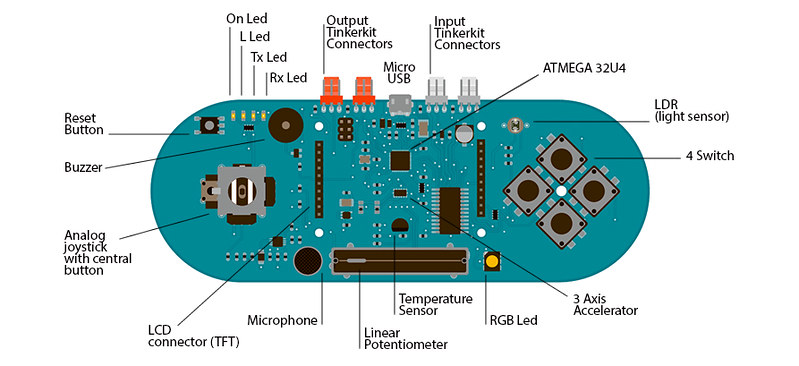
The Esplora has onboard sound and light outputs, and several input sensors, including a joystick, a slider, a temperature sensor, an accelerometer, a microphone, and a light sensor. It also has the potential to expand its capabilities with two Tinkerkit input and output connectors, and a socket for a color TFT LCD screen.
Like the Leonardo board, the Esplora uses an Atmega32U4 AVR microcontroller with 16 MHz crystal oscillator and a micro USB connection capable of acting as a USB client device, like a mouse or a keyboard.
In the upper left corner of the board there is a reset pushbutton, that you can use to restart the board. There are four status LEDS :
- ON [green] indicates whether the board is receiving power supply
- L [yellow] connected directly to the microcontroller, accessible through pin 13
- RX and TX [yellow] indicates the data being transmitted or received over the USB communication
The board contains everything needed to support the microcontroller; simply connect it to a computer with a USB cable to get started.
Schematic & Reference Design
EAGLE files: Attach:arduino-esplora-reference-design.zip
Schematic: Attach:arduino-esplora-schematic.pdf
Memory
The ATmega32u4 has 32 KB (with 4 KB used for the bootloader). It also has 2.5 KB of SRAM and 1 KB of EEPROM (which can be read and written with the EEPROM library).
Input and Output:
The design of the Esplora board recalls traditional gamepad design with an analog joystick on the left and four pushbuttons on the right.
The Esplora has the following on-board inputs and outputs :
- Analog joystick with central push-button two axis (X and Y) and a center pushbutton.
- 4 push-buttons laid out in a diamond pattern.
- Linear potentiometer slider near the bottom of the board.
- Microphone for getting the loudness (amplitude) of the surrounding environment.
- Light sensor for getting the brightness.
- Temperature sensor reads the ambient temperature
- Three-axis accelerometer measures the board’s relation to gravity on three axes (X, Y, and Z)
- Buzzer can produce square-waves.
- RGB led bright LED with Red Green and Blue elements for color mixing.
- 2 TinkerKit Inputs to connect the TinkerKit sensor modules with the 3-pin connectors.
- 2 TinkerKit Outputs to connect the TinkerKit actuator modules with the 3-pin connectors.
- TFT display connector connector for an optional color LCD screen, SD card, or other devices that use the SPI protocol.
In order to utilize the total number of available sensors, the board uses an analog multiplexer. This means a single analog input of the microcontroller is shared among all the input channels (except the 3-axis accelerometer). Four additional microcontroller pins choose which channel to read.
Communication
The Leonardo the Esplora has a number of facilities for communicating with a computer, another Arduino, or other microcontrollers. The ATmega32U4 provides serial (CDC) communication over USB and appears as a virtual com port to software on the computer. The chip also acts as a full speed USB 2.0 device, using standard USB COM drivers. On Windows, a .inf file is required. The Arduino software includes a serial monitor which allows simple textual data to be sent to and from the Arduino board. The RX and TX LEDs on the board will flash when data is being transmitted via the USB connection to the computer.
The ATmega32U4 also supports SPI communication, that can be accessed through the SPI library.
The Esplora can appear as a generic keyboard and mouse, and can be programmed to control these input devices using theKeyboard and Mouse libraries.
Programming
The Esplora can be programmed with the Arduino software (download). Select «Arduino Esplora» from the Tools > Board menu. For details, see the getting started page.
The ATmega32U4 on the Arduino Esplora comes preburned with a bootloader that allows you to upload new code to it without the use of an external hardware programmer. It communicates using the AVR109 protocol.
You can also bypass the bootloader and program the microcontroller through the ICSP (In-Circuit Serial Programming) header; see these instructions for details.
Esplora Library
To facilitate writing sketches for the Esplora, there is a dedicated library that contains methods for reading the sensors and writing to the outputs on-board.
The library offers high level methods which provide pre-processed data, like degrees Fahrenheit or Celsius from the temperature sensor. It also enables easy access to the outputs, like writing values to the RGB LED.
Visit the Esplora library reference page to see the complete documentation of the library and examples.
Automatic (Software) Reset and Bootloader Initiation
Rather than requiring a physical press of the reset button before an upload, the Esplora is designed in a way that allows it to be reset by software running on a connected computer. The reset is triggered when the Esplora’s virtual (CDC) serial / COM port is opened at 1200 baud and then closed. When this happens, the processor will reset, breaking the USB connection to the computer (meaning that the virtual serial / COM port will disappear). After the processor resets, the bootloader starts, remaining active for about 8 seconds. The bootloader can also be initiated by pressing the reset button on the Esplora. Note that when the board first powers up, it will jump straight to the user sketch, if present, rather than initiating the bootloader.
Because of the way the Esplora handles reset it’s best to let the Arduino software try to initiate the reset before uploading, especially if you are in the habit of pressing the reset button before uploading on other boards. If the software can’t reset the board you can always start the bootloader by pressing the reset button on the board.
USB Overcurrent Protection
The Esplora has a resettable polyfuse that protects your computer’s USB ports from shorts and overcurrent. Although most computers provide their own internal protection, the fuse provides an extra layer of protection. If more than 500 mA is applied to the USB port, the fuse will automatically break the connection until the short or overload is removed.
Physical Characteristics
The maximum length and width of the Esplora PCB are 6.5 and 2.4 inches respectively, with the USB and TinkerKitconnectors extending beyond the latter dimension. Four screw holes allow the board to be attached to a surface or case.
Arduino Original DUE

La placa Arduino DUE es la nueva adición a la familia Arduino. Esta es la primera tarjeta que utiliza el procesador con núcleo ARM de 32 bits Atmel SAM3X8E ARM Cortex-M3 MCU, lo cual mejora las capacidades estándard de Arduino y añade nuevas y emocionantes características.
La tarjeta dispone de 54 entradas/salidas digitales (de las cuales 12 se pueden utilizar como salida PWM, con la posibilidad de elegir la resolución), 12 entradas analógicas con resolución de 12 bits, 4 UARTs (puertos serie de hardware), 2 salida DAC (convertidores de analógico a digital), velocidad del reloj de 84 MHz, 2 conectores USB, un conector de alimentación, un conector ICSP, un conector JTAG y un botón de reset (reinicio). La tensión máxima de los pines de Entrada/Salida es de 3,3 Voltios. Nunca utilizar un voltaje más alto, tales como 5 Voltios en un pin de entrada, puesto que puede causar daños a la placa.
Uno de los dos conectores USB, el micro-USB es el nativo y puede funcionar como un host USB. Esto significa que se puede conectar otros dispositivos USB a la tarjeta, tal como ratones, teclados y teléfonos inteligentes. El otro conector USB, de tipo B, se ha diseñado con fines de debug (verificar la operación del programa, probar e interceptar posibles errores.
The Due has two usb connectors, the one with the micro-usb AB connector is the native one capable to act as an USB host, that means you can connect compatible external usb peripherals to the board, such as mouse, keyboards, smartphones. While the other USB port with the type B connector is intended for debugging purposes. If you want to give a closer look to this board we advise you to visit the officialArduino Due page in the Products Section.
Technical Specifications
| Microcontroller | AT91SAM3X8E |
| Operating Voltage | 3.3V |
| Input Voltage (recommended) | 7-12V |
| Input Voltage (limits) | 6-20V |
| Digital I/O Pins | 54 (of which 12 provide PWM output) |
| Analog Input Pins | 12 |
| Analog Outputs Pins | 2 (DAC) |
| Total DC Output Current on all I/O lines | 130 mA |
| DC Current for 3.3V Pin | 800 mA |
| DC Current for 5V Pin | 800 mA |
| SRAM | 96 KB (64 + 32 KB) |
| Clock Speed | 84 MHz |
Arduino Original Ethernet Rev3 + usb 2 Serial

El Arduino Ethernet es una placa electrónica basada en el Arduino Uno, que incorpora una Ethernet W5100 WIZnet TCP / IP integrado. Se puede programar como una UNO a través de una serie de seis pines FTDI. Se puede utilizar el adaptador Arduino USB 2 Serial o cualquier tipo de cable FTDI para actuar como un convertidor de USB a puerto serie.
Las características adicionales que vienen con la versión R3 son:
- 1.0 pinout: añadido SDA y SCL pines para TWI comunicación colocada cerca al pine AREF y dos pasadores de otras nuevas colocadas cerca del pine RESET,se han colocado otros dos nuevos pines, el IOREF que permiten que los escudos para adaptarse a la tensión proporcionada por la junta directiva y el segundo un no conectado pine, que se reserva para usos futuros.
- REINICIO forzado del circuito.
Incluye en el precio el módulo Arduino USB 2 Serial Converter necesario para su programación por cable USB.
A separate power-over-Ethernet (PoE) module can be soldered to the board to provide power from a conventional twisted pair Category 5 Ethernet cable. It is IEEE802.3af compliant, and works with all compliant PoE injectors currently available. Additional features coming with the R3 version are:
- 1.0 pinout: added SDA and SCL pins for TWI communication placed near to the AREF pin and two other new pins placed near to the RESET pin, the IOREF that allow the shields to adapt to the voltage provided from the board and the second one is a not connected pin, that is reserved for future purposes.
- stronger RESET circuit.
Technical Specifications
| Microcontroller | ATmega328 |
| Operating Voltage | 5V |
| Input Voltage (recommended) | 7-12V |
| Input Voltage (limits) | 6-20V |
| Digital I/O Pins | 14 (of which 4 provide PWM output) |
| Analog Input Pins | 6 |
| DC Current per I/O Pin | 40 mA |
| DC Current for 3.3V Pin | 50 mA |
| Flash Memory | 32 KB (ATmega328) of which 0.5 KB used by bootloader |
| SRAM | 2 KB (ATmega328) |
| EEPROM | 1 KB (ATmega328) |
| Clock Speed | 16 MHz |
| W5100 TCP/IP Embedded Ethernet Controller | |
| Power Over Ethernet ready Magnetic Jack | |
| Micro SD card, with active voltage translators |
Arduino Pins reserved
- 10 to 13 used for SPI
- 4 used for SD card
- 2 W5100 interrupt (when bridged)
Arduino Original Ethernet Shield Rev3

The Arduino Ethernet Shield allows an Arduino board to connect to the internet. It is based on the Wiznet W5100 ethernet chip (datasheet). The Wiznet W5100 provides a network (IP) stack capable of both TCP and UDP. It supports up to four simultaneous socket connections. Use the Ethernet library to write sketches which connect to the internet using the shield. The ethernet shield connects to an Arduino board using long wire-wrap headers which extend through the shield. This keeps the pin layout intact and allows another shield to be stacked on top.
The R3 version brings to this shield the 1.0 standard pinout that consist in 4 additional pins: 2 of them placed near the AREF pin, that are used for TWI communication, and the other 2 are placed near the RESET pin. The IOREF pin is used to adapt the shield to the board on which is mounted. The last one is not connected and is reserved for future uses. The latest revision of the shield adds a micro-SD card slot, which can be used to store files for serving over the network. It is compatible with the Arduino Duemilanove and Mega (using the Ethernet library). It also adds a separate power-over-Ethernet (PoE) module can be soldered to the board to provide power from a conventional twisted pair Category 5 Ethernet cable. It is IEEE802.3af compliant, and works with all compliant PoE injectors currently available.
Arduino Original Leonardo (+headers)
")
Arduino Leonardo es una placa de prototipado electrónico que lleva un microprocesador integrado basado en el ATmega32u4 (datasheet). Tiene 20 entradas/salidas digitales (7 de las cuales se pueden utilizar como salidas PWM) y 12 entradas analogicas, un oscilador de cristal de 16 MHz, un conector micro USB, un conector para la fuente de alimentación, un conector ISCP y un pulsador para el reset. La placa lleva todos los componentes que necesita el microcontrolador para funcionar; simplemente conéctela a tu ordenador con un cable USB o alimentala mediante un adaptador de red (AC/DC) o con un paquete de baterías y ya estarás listo para empezar.
Arduino Leonardo difiere de todas las otras placas anteriores, por el hecho de que el ATmega32u4 tiene ya en su interior la parte de comunicación USB, así que se elimina la necesidad de un microprocesador secundario. Esto permite que Leonardo, una vez conectado a un ordenador, se reconozca como un ratón o un teclado, y también emula permanentemente un puerto de serie (CDC) / COM port.
If you want to give a closer look to this board we advise you to visit the officialArduino Leonardo page in the Hardware Section.
The Leonardo differs from all preceding boards in that the ATmega32u4 has built-in USB communication, eliminating the need for a secondary processor. This allows the Leonardo to appear to a connected computer as a mouse and keyboard, in addition to a virtual (CDC) serial / COM port. It also has other implications for the behavior of the board; these are detailed on the getting started page. This version of the Leonardo comes assembled.
Summary
| Microcontroller | ATmega32u4 |
| Operating Voltage | 5V |
| Input Voltage (recommended) | 7-12V |
| Input Voltage (limits) | 6-20V |
| Digital I/O Pins | 20 |
| PWM Channels | 7 |
| Analog Input Channels | 12 |
| DC Current per I/O Pin | 40 mA |
| DC Current for 3.3V Pin | 50 mA |
| Flash Memory | 32 KB (ATmega32u4) of which 4 KB used by bootloader |
| SRAM | 2.5 KB (ATmega32u4) |
| EEPROM | 1 KB (ATmega32u4) |
| Clock Speed | 16 MHz |
Arduino Original Mega2560 Rev3

La Arduino Mega 2560 es una placa electrónica basada en el microprocesador Atmega2560 (datasheet). Cuenta con 54 entradas / salidas digitales pines (de los cuales 14 se pueden utilizar como salidas PWM), 16 entradas analógicas,4 UARTs (puertos serie de hardware), un oscilador de cristal de 16 MHz, una conexión USB, un conector de alimentación, un conector ICSP y un botón de reset. Contiene todo lo necesario para apoyar el microcontrolador, basta con conectarlo a un ordenador con un cable USB o el poder con un adaptador de AC a DC o batería para empezar.La Mega es compatible con la mayoría de los shilds diseñados para el Arduino Uno, Duemilanove o Diecimila.
If you want to give a closer look to this board we advice you to visit the officialArduino Mega 2560 page in the Hardware Section.
The Mega 2560 is an update to the Arduino Mega, which it replaces. Additional features coming with the R3 version are:
- ATmega16U2 instead 8U2 as USB-to-Serial converter.
- 1.0 pinout: added SDA and SCL pins for TWI communication placed near to the AREF pin and two other new pins placed near to the RESET pin, the IOREF that allow the shields to adapt to the voltage provided from the board and the second one is a not connected pin, that is reserved for future purposes.
- stronger RESET circuit.
| Microcontroller | ATmega2560 |
| Operating Voltage | 5V |
| Input Voltage (recommended) | 7-12V |
| Input Voltage (limits) | 6-20V |
| Digital I/O Pins | 54 (of which 14 provide PWM output) |
| Analog Input Pins | 16 |
| DC Current per I/O Pin | 40 mA |
| DC Current for 3.3V Pin | 50 mA |
| Flash Memory | 256 KB of which 8 KB used by bootloader |
| SRAM | 8 KB |
| EEPROM | 4 KB |
| Clock Speed | 16 MHz |
Arduino Original Nano

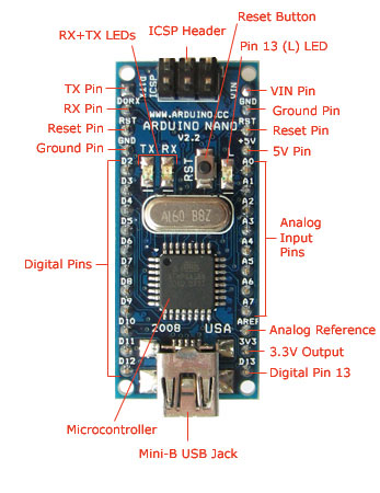
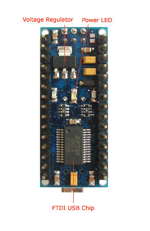
El Arduino Nano es una pequeña y completa placa basada en el ATmega328 (Arduino Nano 3.0) o ATmega168 (Arduino Nano 2.x) que se usa conectándola a una protoboard. Tiene más o menos la misma funcionalidad que el Arduino Duemilanove, pero con una presentación diferente. No posee conector para alimentación externa, y funciona con un cable USB Mini-B en vez de el cable estandar. El nano fue diseñado y está siendo producido por Gravitech.
Since the Nano is automatically sense and switch to the higher potential source of power, there is no need for the power select jumper. The Arduino Nano is a small, complete, and breadboard-friendly board based on the ATmega328 (Arduino Nano 3.0) orATmega168 (Arduino Nano 2.x). It has more or less the same functionality of the Arduino Duemilanove, but in a different package. It lacks only a DC power jack, and works with a Mini-B USB cable instead of a standard one. The Nano was designed and is being produced by Gravitech.
 |
 |
Schematic and Design
Arduino Nano 3.0 (ATmega328): schematic, Eagle files. Operating Voltage (logic level)5 VInput Voltage (recommended)7-12 VInput Voltage (limits)6-20 VDigital I/O Pins14 (of which 6 provide PWM output)Analog Input Pins8DC Current per I/O Pin40 mAFlash Memory16 KB (ATmega168) or 32 KB (ATmega328) of which 2 KB used by bootloaderSRAM1 KB (ATmega168) or 2 KB (ATmega328)EEPROM512 bytes (ATmega168) or 1 KB (ATmega328)Clock Speed16 MHzDimensions0.73″ x 1.70″Arduino Original Proto Shield

The Arduino Prototyping Shield makes it easy for you to design custom circuits. You can solder parts to the prototyping area to create your project, or use it with a small solderless breadboard (not included) to quickly test circuit ideas without having to solder. It’s got extra connections for all of the Arduino I/O pins, and it’s got space to mount through-hole and surface mount integrated circuits. It’s a convenient way to make your custom circuit and Arduino into a single module.
Summary
A wide prototyping area with some extra features:| 1.0 | Arduino pinout |
| 1 | Reset button |
| 1 | ICSP connector |
| 14 | pin SMD footprint (50 mils pitch) |
| 20 | pin Through Hole footprint (100 mils pitch) |
Schematic & Reference Design
EAGLE files: arduino_ProtoShield_Rev3.zip Schematic: arduino_ProtoShield_Rev3-schematic.pdfPower
The Proto Shield bring the power from the Arduino standard 5V and GND pins to the two power bus rows placed between the Through Hole package footprint, which can be used for powering the DIP sockets, or for power and ground rows.SPI connection
The ICSP connector available on the shield hove his connections made directly to the SPI pins.- 1: (the one with the smal pointer sign) MISO connected to D12
- 2: +5V
- 3: SCK connected to D13
- 4: MOSI connected to D11
- 5: SS connected to D10
- 6: GND
Physical Characteristics
The maximum length and width of the Proto Shield PCB are 2.7 and 2.1 inches respectively. Three screw holes allow the shield to be attached to a surface or case. Note that the distance between digital pins 7 and 8 is 160 mil (0.16″), not an even multiple of the 100 mil spacing of the other pins.Arduino Original Uno R3

The Arduino Uno is a microcontroller board based on the ATmega328 (datasheet). It has 14 digital input/output pins (of which 6 can be used as PWM outputs), 6 analog inputs, a 16 MHz ceramic resonator, a USB connection, a power jack, an ICSP header, and a reset button. It contains everything needed to support the microcontroller; simply connect it to a computer with a USB cable or power it with a AC-to-DC adapter or battery to get started.
The Uno differs from all preceding boards in that it does not use the FTDI USB-to-serial driver chip. Instead, it features the Atmega16U2 (Atmega8U2 up to version R2) programmed as a USB-to-serial converter. Revision 2 of the Uno board has a resistor pulling the 8U2 HWB line to ground, making it easier to put into . Revision 3 of the board has the following new features:
- 1.0 pinout: added SDA and SCL pins that are near to the AREF pin and two other new pins placed near to the RESET pin, the IOREF that allow the shields to adapt to the voltage provided from the board. In future, shields will be compatible both with the board that use the AVR, which operate with 5V and with the Arduino Due that operate with 3.3V. The second one is a not connected pin, that is reserved for future purposes.
- Stronger RESET circuit.
- Atmega 16U2 replace the 8U2.
Summary
| Microcontroller | ATmega328 |
| Operating Voltage | 5V |
| Input Voltage (recommended) | 7-12V |
| Input Voltage (limits) | 6-20V |
| Digital I/O Pins | 14 (of which 6 provide PWM output) |
| Analog Input Pins | 6 |
| DC Current per I/O Pin | 40 mA |
| DC Current for 3.3V Pin | 50 mA |
| Flash Memory | 32 KB (ATmega328) of which 0.5 KB used by bootloader |
| SRAM | 2 KB (ATmega328) |
| EEPROM | 1 KB (ATmega328) |
| Clock Speed | 16 MHz |
Arduino Original Uno SMD Rev3

The Arduino Uno SMD R3 is a microcontroller board based on the ATmega328 (datasheet). It has 14 digital input/output pins (of which 6 can be used as PWM outputs), 6 analog inputs, a 16 MHz crystal oscillator, a USB connection, a power jack, an ICSP header, and a reset button. It contains everything needed to support the microcontroller; simply connect it to a computer with a USB cable or power it with a AC-to-DC adapter or battery to get started.
The Uno differs from all preceding boards in that it does not use the FTDI USB-to-serial driver chip.
If you want to give a closer look to this board we advice you to visit the official Arduino UNO page in the Hardware Section.
Additional features coming with the R3 version are:
- ATmega16U2 instead 8U2 as USB-to-Serial converter.
- 1.0 pinout: added SDA and SCL pins for TWI communication placed near to the AREF pin and two other new pins placed near to the RESET pin, the IOREF that allow the shields to adapt to the voltage provided from the board and the second one is a not connected pin, that is reserved for future purposes.
- stronger RESET circuit.
Technical Specifications
| Microcontroller | ATmega328 |
| Operating Voltage | 5V |
| Supply Voltage (recommended) | 7-12V |
| Maximum supply voltage (not recommended) | 20V |
| Digital I/O Pins | 14 (of which 6 provide PWM output) |
| Analog Input Pins | 6 |
| DC Current per I/O Pin | 40 mA |
| DC Current for 3.3V Pin | 50 mA |
| Flash Memory | 32 KB (ATmega328) of which 0.5 KB used by bootloader |
| SRAM | 2 KB (ATmega328) |
| EEPROM | 1 KB (ATmega328) |
| Clock Speed | 16 MHz |
Arduino Original USB 2 Serial Converter

This board converts a USB connection into 5 volt TX and RX that you can connect straight to the Arduino Ethernet or any other boards with an FTDI cable-compatible connector.
It features the Atmega8U2 programmed as a USB-to-serial converter, the same chip found on the Arduino Uno. The USB Serial module has an ISCP interface, allowing you to reprogram the chip when placed in DFU mode.
The pinouts on the connector are compatible with a standard FTDI header (as well as the Adafruit and Sparkfun USB-Serial adapters).
Arduino YÚN

Overview
The Arduino Yún is a microcontroller board based on the ATmega32u4 (datasheet) and the Atheros AR9331. The Atheros processor supports a Linux distribution based on OpenWRT named Linino. The board has built-in Ethernet and WiFisupport, a USB-A port, micro-SD card slot, 20 digital input/output pins (of which 7 can be used as PWM outputs and 12 as analog inputs), a 16 MHz crystal oscillator, a micro USB connection, an ICSP header, and a 3 reset buttons.
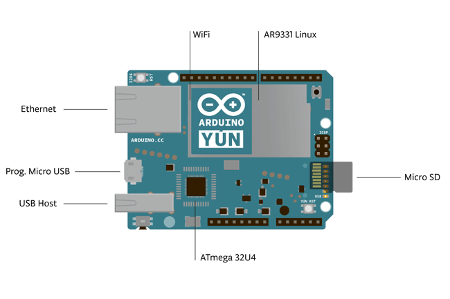
The Yún distinguishes itself from other Arduino boards in that it can communicate with the Linux distribution onboard, offering a powerful networked computer with the ease of Arduino. In addition to Linux commands like cURL, you can write your own shell and python scripts for robust interactions.
The Yún is similar to the Leonardo in that the ATmega32u4 has built-in USB communication, eliminating the need for a secondary processor. This allows the Yún to appear to a connected computer as a mouse and keyboard, in addition to a virtual (CDC) serial / COM port.
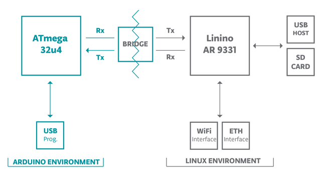
The Bridge library facilitates communication between the two processors, giving Arduino sketches the ability to run shell scripts, communicate with network interfaces, and receive information from the AR9331 processor. The USB host, network interfaces and SD card are not connected to the 32U4, but the AR9331, and the Bridge library also enables the Arduino to interface with those peripherals.
Summary
Because the Yún has two processors, the summary section shows the characteristics of each one in two separate tables.| AVR Arduino microcontroller | |
| Microcontroller | ATmega32u4 |
| Operating Voltage | 5V |
| Input Voltage | 5V |
| Digital I/O Pins | 20 |
| PWM Channels | 7 |
| Analog Input Channels | 12 |
| DC Current per I/O Pin | 40 mA |
| DC Current for 3.3V Pin | 50 mA |
| Flash Memory | 32 KB (of which 4 KB used by bootloader) |
| SRAM | 2.5 KB |
| EEPROM | 1 KB |
| Clock Speed | 16 MHz |
| Linux microprocessor | |
| Processor | Atheros AR9331 |
| Architecture | MIPS @400MHz |
| Operating Voltage | 3.3V |
| Ethernet | IEEE 802.3 10/100Mbit/s |
| WiFi | IEEE 802.11b/g/n |
| USB Type-A | 2.0 Host/Device |
| Card Reader | Micro-SD only |
| RAM | 64 MB DDR2 |
| Flash Memory | 32 MB |
| PoE compatible 802.3af card support |
Schematic & Reference Design
Schematic: arduino-Yun-schematic.pdfPower
It is recommended to power the board via the micro-USB connection with 5VDC.
If you are powering the board though the Vin pin, you must supply a regulated 5VDC. There is no on-board voltage regulator for higher voltages, which will damage the board.
The Yún is also compatible with PoE power supply but in order to use this feature you need to mount a PoE module on the board or buy a preassembled one.
The power pins are as follows:
- VIN. The input voltage to the Arduino board. Unlike other Arduino boards, if you are going to provide power to the board through this pin, you must provide a regulated 5V.
- 5V. The power supply used to power the microcontrollers and other components on the board. This can come either from VIN or be supplied by USB.
- 3V3. A 3.3 volt supply generated by the on-board regulator. Maximum current draw is 50 mA.
- GND. Ground pins.
- IOREF. The voltage at which the i/o pins of the board are operating (i.e. VCC for the board). This is 5V on the Yún.
Memory
The ATmega32u4 has 32 KB (with 4 KB used for the bootloader). It also has 2.5 KB of SRAM and 1 KB of EEPROM (which can be read and written with the EEPROM library).
The memory on the AR9331 is not embedded inside the processor. The RAM and the storage memory are externally connected. The Yún has 64 MB of DDR2 RAM and 16 MB of flash memory. The flash memory is preloaded in factory with a Linux distribution based on OpenWRT called Linino. You can change the content of the factory image, such as when you install a program or when you change a configuration file. You can return to the factory configuration by pressing the «WLAN RST» button for 30 seconds.
Input and Output
It is not possible to access the I/O pins of the Atheros AR9331. All I/O lines are tied to the 32U4.
Each of the 20 digital i/o pins on the Yún can be used as an input or output, using pinMode(), digitalWrite(), anddigitalRead() functions. They operate at 5 volts. Each pin can provide or receive a maximum of 40 mA and has an internal pull-up resistor (disconnected by default) of 20-50 kOhms. In addition, some pins have specialized functions:
- Serial: 0 (RX) and 1 (TX). Used to receive (RX) and transmit (TX) TTL serial data using the ATmega32U4 hardware serial capability. Note that on the Yún, the Serial class refers to USB (CDC) communication; for TTL serial on pins 0 and 1, use the Serial1 class. The hardware serials of the ATmega32U4 and the AR9331 on the Yún are connected together and are used to communicate between the two processors. As is common in Linux systems, on the serial port of the AR9331 is exposed the console for access to the system, this means that you can access to the programs and tools offered by Linux from your sketch.
- TWI: 2 (SDA) and 3 (SCL). Support TWI communication using the Wire library.
- External Interrupts: 3 (interrupt 0), 2 (interrupt 1), 0 (interrupt 2), 1 (interrupt 3) and 7 (interrupt 4). These pins can be configured to trigger an interrupt on a low value, a rising or falling edge, or a change in value. See the attachInterrupt() function for details. Is not recommended to use pins 0 and 1 as interrupts because they are the also the hardware serial port used to talk with the Linux processor. Pin 7 is connected to the AR9331 processor and it may be used as handshake signal in future. Is recommended to be careful of possible conflicts if you intend to use it as interrupt.
- PWM: 3, 5, 6, 9, 10, 11, and 13. Provide 8-bit PWM output with the analogWrite() function.
- SPI: on the ICSP header. These pins support SPI communication using the SPI library. Note that the SPI pins are not connected to any of the digital I/O pins as they are on the Uno, They are only available on the ICSP connector. This means that if you have a shield that uses SPI, but does NOT have a 6-pin ICSP connector that connects to the Yún’s 6-pin ICSP header, the shield will not work.
The SPI pins are also connected to the AR9331 gpio pins, where it has been implemented in software the SPI interface. This means that the ATMega32u4 and the AR9331 can also communicate using the SPI protocol.
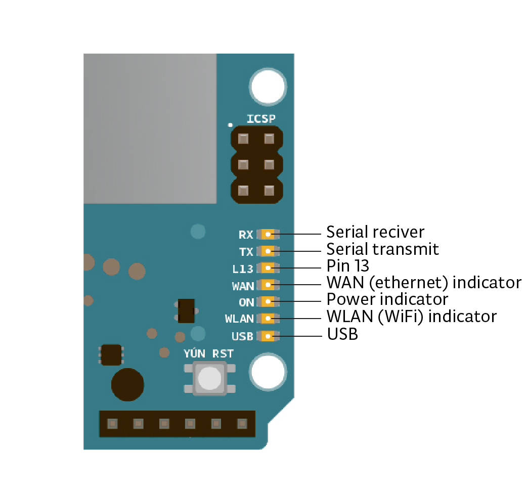
- LED: 13. There is a built-in LED connected to digital pin 13. When the pin is HIGH value, the LED is on, when the pin is LOW, it’s off.
- There are several other status LEDs on the Yún, indicating power, WLAN connection, WAN connection and USB.
- Analog Inputs: A0 – A5, A6 – A11 (on digital pins 4, 6, 8, 9, 10, and 12). The Yún has 12 analog inputs, labeled A0 through A11, all of which can also be used as digital i/o. Pins A0-A5 appear in the same locations as on the Uno; inputs A6-A11 are on digital i/o pins 4, 6, 8, 9, 10, and 12 respectively. Each analog input provide 10 bits of resolution (i.e. 1024 different values). By default the analog inputs measure from ground to 5 volts, though is it possible to change the upper end of their range using the AREF pin and the analogReference() function.
- AREF. Reference voltage for the analog inputs. Used with analogReference().
There are 3 reset buttons with different functions on the board:
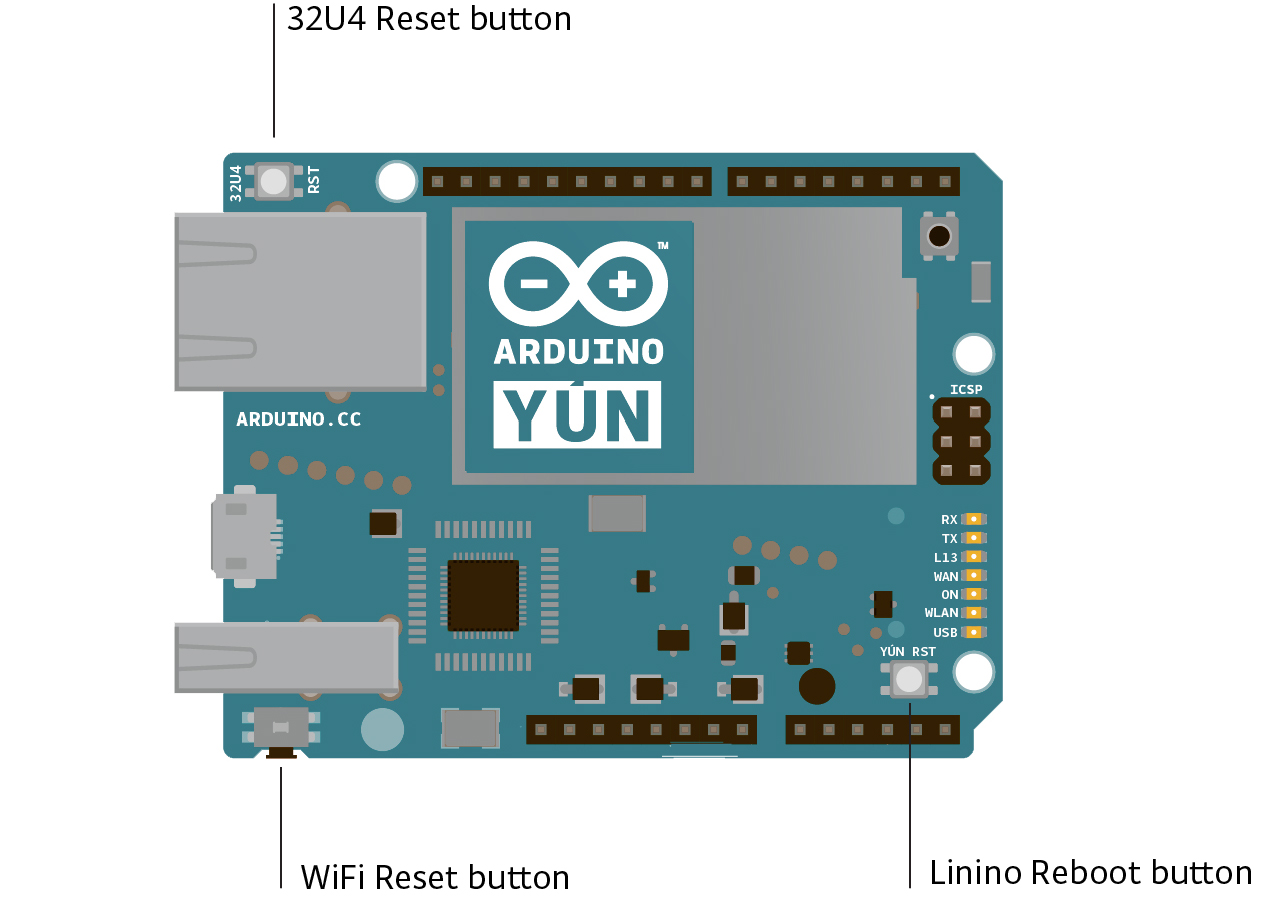
- Yún RST. Bring this line LOW to reset the AR9331 microprocessor. Resetting the AR9331 will cause the reboot of the linux system. All the data stored in RAM will be lost and all the programs that are running will be terminated.
- 32U4 RST. Bring this line LOW to reset the ATmega32U4 microcontroller. Typically used to add a reset button to shields which block the one on the board.
- WLAN RST. This button has a double feature. Primarly serves to restore the WiFi to the factory configuration. The factory configuration consist to put the WiFi of the Yún in access point mode (AP) and assign to it the default IP address that is 192.168.240.1, in this condition you can connect with your computer to the a WiFi network that appear with the SSID name «Arduino Yun-XXXXXXXXXXXX», where the twelve ‘X’ are the MAC address of your Yún. Once connected you can reach the web panel of the Yún with a browser at the 192.168.240.1 or «http://arduino.local» address. Note that restoring the WiFi configuration will cause the reboot of the linux environment. To restore your WiFi configuration you have to press and hold the WLAN RST button for 5 seconds. When you press the button the WLAN blue LED will start to blink and will keep still blinking when you release the button after 5 seconds indicating that the WiFi restore procedure has been recorded. The second function of the WLAN RST button is torestore the linux image to the default factory image. To restore the linux environment you must press the button for 30 seconds. Note that restoring the factory image make you lose all the files saved and softwares installed on the on-board flash memory connected to the AR9331.
See also the mapping between Arduino pins and ATmega32u4 ports.
Communication
The Yún has a number of facilities for communicating with a computer, another Arduino, or other microcontrollers. TheATmega32U4 provides a dedicated UART TTL (5V) serial communication. The 32U4 also allows for serial (CDC) communication over USB and appears as a virtual com port to software on the computer. The chip also acts as a full speed USB 2.0 device, using standard USB COM drivers. The Arduino software includes a serial monitor which allows simple textual data to be sent to and from the Arduino board. The RX and TX LEDs on the board will flash when data is being transmitted via the USB connection to the computer.
Digital pins 0 and 1 are used for serial communication between the 32U4 and the AR9331. Communication between the processors is handled by the Bridge library.
A SoftwareSerial library allows for serial communication on any of the Yún’s digital pins except for pins 0 and 1.
The ATmega32U4 also supports I2C (TWI) and SPI communication. The Arduino software includes a Wire library to simplify use of the I2C bus; see the documentation for details. For SPI communication, use the SPI library.
The Yún appears as a generic keyboard and mouse, and can be programmed to control these input devices using theKeyboard and Mouse classes.
The onboard Ethernet and WiFi interfaces are exposed directly to the AR9331 processor. To send and receive data through them, use the Bridge library. To configure the interfaces, you can access the network control panel as described in thegetting started page.
The Yún also has USB host capabilities through Linino. You can connect peripherals like USB flash devices for additional storage, keyboards, or webcams. You may need to download and install additional software for these devices to work. For information on adding software to the AR9331, refer to the notes on using the package manager.
Programming
The Yún can be programmed with the Arduino software (download). Select «Arduino Yún from the Tools > Board menu (according to the microcontroller on your board). For details, see the reference and tutorials.
The ATmega32U4 on the Arduino Yún comes preburned with a bootloader that allows you to upload new code to it without the use of an external hardware programmer. It communicates using the AVR109 protocol.
You can also bypass the bootloader and program the microcontroller through the ICSP (In-Circuit Serial Programming) header; see these instructions for details.
Automatic (Software) Reset and Bootloader Initiation
Rather than requiring a physical press of the reset button before an upload, the Yún is designed in a way that allows it to be reset by software running on a connected computer. The reset is triggered when the Yún’s virtual (CDC) serial / COM port is opened at 1200 baud and then closed. When this happens, the processor will reset, breaking the USB connection to the computer (meaning that the virtual serial / COM port will disappear). After the processor resets, the bootloader starts, remaining active for about 8 seconds. The bootloader can also be initiated by pressing the reset button on the Yún. Note that when the board first powers up, it will jump straight to the user sketch, if present, rather than initiating the bootloader.
Because of the way the Yún handles reset it’s best to let the Arduino software try to initiate the reset before uploading, especially if you are in the habit of pressing the reset button before uploading on other boards. If the software can’t reset the board you can always start the bootloader by pressing the reset button on the board.
USB Overcurrent Protection
The Yún has a resettable polyfuse that protects your computer’s USB ports from shorts and overcurrent. Although most computers provide their own internal protection, the fuse provides an extra layer of protection. If more than 500 mA is applied to the USB port, the fuse will automatically break the connection until the short or overload is removed.
Physical Characteristics
The maximum length and width of the Yún PCB are 2.7 and 2.1 inches respectively, with the USB connector extending beyond the former dimension. Four screw holes allow the board to be attached to a surface or case. Note that the distance between digital pins 7 and 8 is 160 mil (0.16″), not an even multiple of the 100 mil spacing of the other pins.
Using your Yun
There is an extensive Getting Started Guide and a number of tutorials found on the library reference page.