
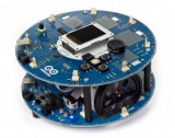
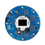
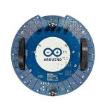
El Arduino Robot es la primera Arduino oficial sobre ruedas. El robot tiene dos procesadores, uno en cada uno de sus dos tableros. El motor board controla los motores y el Control Board lee sensores y decide cómo operar. Cada una de las tablas es una placa Arduino completa programable utilizando el IDE Arduino.
Tanto el motor y tableros de control son placas de microcontroladores basados en el ATMEGA32U4 (hoja de datos). El robot tiene muchos de sus pines asignados a los sensores de a bordo y actuadores.
La programación del robot es similar al proceso con el Arduino Leonardo. Ambos procesadores han incorporado en comunicación USB, eliminando la necesidad de un procesador secundario. Esto permite que el robot que aparezca como un ordenador conectado como un puerto serie/COM virtual (CDC).
Como siempre con Arduino, todos los elementos de la plataforma - hardware, software y documentación - es de libre acceso y de código abierto. Esto significa que usted puede aprender exactamente cómo se hace y utilizar su diseño como punto de partida para sus propios robots. El Arduino Robot es el resultado del esfuerzo colectivo de un equipo internacional que mira cómo la ciencia puede ser divertida de aprender. Arduino está ahora sobre ruedas y viene paseo con nosotros!
vía Arduino - Robot.
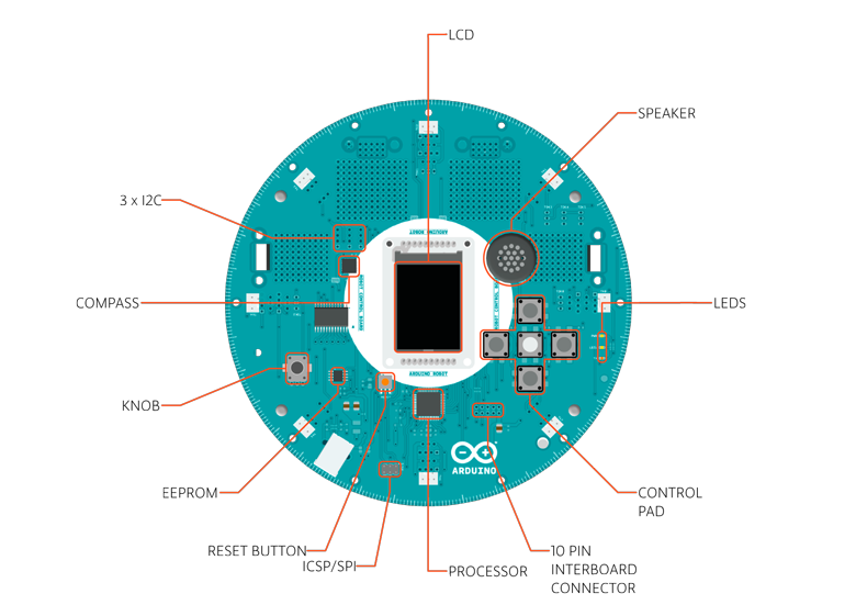
Control Board Summary
| Microcontroller | ATmega32u4 |
| Operating Voltage | 5V |
| Input Voltage | 5V through flat cable |
| Digital I/O Pins | 5 |
| PWM Channels | 6 |
| Analog Input Channels | 4 (of the Digital I/O pins) |
| Analog Input Channels (multiplexed) | 8 |
| DC Current per I/O Pin | 40 mA |
| Flash Memory | 32 KB (ATmega32u4) of which 4 KB used by bootloader |
| SRAM | 2.5 KB (ATmega32u4) |
| EEPROM (internal) | 1 KB (ATmega32u4) |
| EEPROM (external) | 512 Kbit (I2C) |
| Clock Speed | 16 MHz |
| Keypad | 5 keys |
| Knob | potentiomenter attached to analog pin |
| Full color LCD | over SPI communication |
| SD card reader | for FAT16 formatted cards |
| Speaker | 8 Ohm |
| Digital Compass | provides deviation from the geographical north in degrees |
| I2C soldering ports | 3 |
| Prototyping areas | 4 |
Motor Board Summary
| Microcontroller | ATmega32u4 |
| Operating Voltage | 5V |
| Input Voltage | 9V to battery charger |
| AA battery slot | 4 alkaline or NiMh rechargeable batteries |
| Digital I/O Pins | 4 |
| PWM Channels | 1 |
| Analog Input Channles | 4 (same as the Digital I/O pins) |
| DC Current per I/O Pin | 40 mA |
| DC-DC converter | generates 5V to power up the whole robot |
| Flash Memory | 32 KB (ATmega32u4) of which 4 KB used by bootloader |
| SRAM | 2.5 KB (ATmega32u4) |
| EEPROM | 1 KB (ATmega32u4) |
| Clock Speed | 16 MHz |
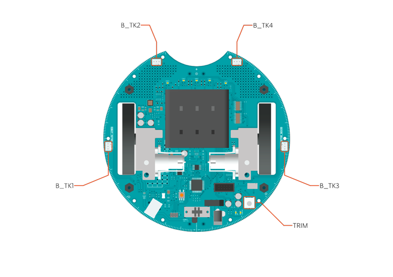
| Trimmer | for movement calibration |
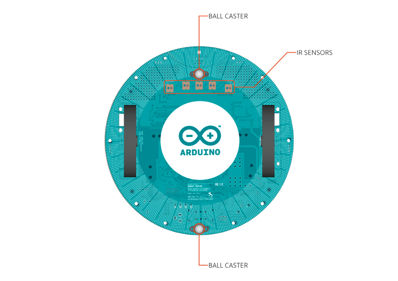
| IR line following sensors | 5 |
| I2C soldering ports | 1 |
| Prototyping areas | 2 |
Schematic & Reference Design
EAGLE files for control and motor boards: arduino-robot-reference-design.zipPower
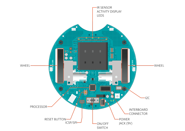
The Arduino Robot can be powered via the USB connection or with 4 AA batteries. The power source is selected automatically. The battery holder holds 4 rechargeable NiMh AA batteries. NB : Do not use non-rechargeable batteries with the robot For safety purposes, the motors are disabled when the robot is powered from the USB connection. The robot has an on-board battery charger that requires 9V external power coming from an AC-to-DC adapter (wall-wart). The adapter can be connected by plugging a 2.1mm center-positive plug into the Motor Board's power jack. The charger will not operate if powered by USB. The Control Board is powered by the power supply on the Motor Board.Memory
The ATmega32u4 has 32 KB (with 4 KB used for the bootloader). It also has 2.5 KB of SRAM and 1 KB of EEPROM (which can be read and written with the EEPROM library). The Control Board has an extra 512 Kbit EEPROM that can be accessed via I2C. There is an external SD card reader attached to the GTFT screen that can be accessed by the Control Board's processor for additional storage.Input and Output
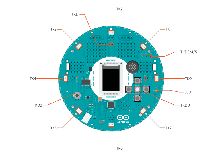
The Robot comes with a series of pre-soldered connectors. There are a number of additional spots for you to install additional parts if needed. All the connectors are labelled on the boards and mapped to named ports through the Robot library allowing access to standard Arduino functions. Each pin can provide or receive a maximum of 40mA at 5V. Some pins have specialized functions :- Control Board TK0 to TK7: these pins are multiplexed to a single analog pin on theControl Board's microprocessor. They can be used as analog inputs for sensors like distance sensors, analog ultrasound sensors, or mechanical switches to detect collisions.
- Control Board TKD0 to TKD5: these are digital I/O pins directly connected to the processor, addressed usingRobot.digitalRead() and Robot.digitalWrite) functions. Pins TKD0 to TKD3 can also be used as analog inputs withRobot.analogRead() Note: if you have one of the first generation robots, you will see that the TKD* pins are named TDK* on the Robot's silkscreen. TKD* is the proper name for them and is how we address them on the software.
- Motor Board TK1 to TK4: these pins are named in software as B_TK1 to B_TK4, they can be digital or analog input pins, and support Robot.digitalRead(), Robot.digitalWrite) and Robot.analogRead().
- Serial Communication: The boards communicate with each other using the processors' serial port. A 10-pin connector connects both boards carries the serial communication, as well as power and additional information like the battery's current charge.
- Control Board SPI: SPI is used to control the GTFT and SD card. If you want to flash the processor using an external programmer, you need to disconnect the screen first
- Control Board LEDs: the Control Board has three on-board LEDs. One indicates the board is powered (PWR). The other two indicate communication over the USB port (LED1/RX and TX). LED1 is also accessible via software.
- Both boards have I2C connectors available: 3 on the Control Board and 1 on the Motor Board.
Control Board Pin Mapping
| ARDUINO LEONARDO | ARDUINO ROBOT CONTROL | ATMEGA 32U4 | FUNCTION | REGISTER |
| D0 | RX | PD2 | RX | RXD1/INT2 |
| D1 | TX | PD3 | TX | TXD1/INT3 |
| D2 | SDA | PD1 | SDA | SDA/INT1 |
| D3# | SCL | PD0 | PWM8/SCL | OC0B/SCL/INT0 |
| D4 | MUX_IN A6 | PD4 | ADC8 | |
| D5# | BUZZ | PC6 | ??? | OC3A/#OC4A |
| D6# | MUXA/TKD4 A7 | PD7 | FastPWM | #OC4D/ADC10 |
| D7 | RST_LCD | PE6 | INT6/AIN0 | |
| D8 | CARD_CS A8 | PB4 | ADC11/PCINT4 | |
| D9# | LCD_CS A9 | PB5 | PWM16 | OC1A/#OC4B/ADC12/PCINT5 |
| D10# | DC_LCD A10 | PB6 | PWM16 | OC1B/0c4B/ADC13/PCINT6 |
| D11# | MUXB | PB7 | PWM8/16 | 0C0A/OC1C/#RTS/PCINT7 |
| D12 | MUXC/TKD5 A11 | PD6 | T1/#OC4D/ADC9 | |
| D13# | MUXD | PC7 | PWM10 | CLK0/OC4A |
| A0 | KEY D18 | PF7 | ADC7 | |
| A1 | TKD0 D19 | PF6 | ADC6 | |
| A2 | TKD1 D20 | PF5 | ADC5 | |
| A3 | TKD2 D21 | PF4 | ADC4 | |
| A4 | TKD3 D22 | PF1 | ADC1 | |
| A5 | POT D23 | PF0 | ADC0 | |
| MISO | MISO D14 | PB3 | MISO,PCINT3 | |
| SCK | SCK D15 | PB1 | SCK,PCINT1 | |
| MOSI | MOSI D16 | PB2 | MOSI,PCINT2 | |
| SS | RX_LED D17 | PB0 | RXLED,SS/PCINT0 | |
| TXLED | TX_LED | PD5 | ||
| HWB | PE2 | HWB |
Motor Board Pin Mapping
| ARDUINO LEONARDO | ARDUINO ROBOT CONTROL | ATMEGA 32U4 | FUNCTION | REGISTER |
| D0 | RX | PD2 | RX | RXD1/INT2 |
| D1 | TX | PD3 | TX | TXD1/INT3 |
| D2 | SDA | PD1 | SDA | SDA/INT1 |
| D3# | SCL | PD0 | PWM8/SCL | OC0B/SCL/INT0 |
| D4 | TK3 A6 | PD4 | ADC8 | |
| D5# | INA2 | PC6 | ??? | OC3A/#OC4A |
| D6# | INA1 A7 | PD7 | FastPWM | #OC4D/ADC10 |
| D7 | MUXA | PE6 | INT6/AIN0 | |
| D8 | MUXB A8 | PB4 | ADC11/PCINT4 | |
| D9# | INB2 A9 | PB5 | PWM16 | OC1A/#OC4B/ADC12/PCINT5 |
| D10# | INB1 A10 | PB6 | PWM16 | OC1B/0c4B/ADC13/PCINT6 |
| D11# | MUXC | PB7 | PWM8/16 | 0C0A/OC1C/#RTS/PCINT7 |
| D12 | TK4 A11 | PD6 | T1/#OC4D/ADC9 | |
| D13# | MUXI | PC7 | PWM10 | CLK0/OC4A |
| A0 | TK1 D18 | PF7 | ADC7 | |
| A1 | TK2 D19 | PF6 | ADC6 | |
| A2 | MUX_IN D20 | PF5 | ADC5 | |
| A3 | TRIM D21 | PF4 | ADC4 | |
| A4 | SENSE_A D22 | PF1 | ADC1 | |
| A5 | SENSE_B D23 | PF0 | ADC0 | |
| MISO | MISO D14 | PB3 | MISO,PCINT3 | |
| SCK | SCK D15 | PB1 | SCK,PCINT1 | |
| MOSI | MOSI D16 | PB2 | MOSI,PCINT2 | |
| SS | RX_LED D17 | PB0 | RXLED,SS/PCINT0 | |
| TXLED | TX_LED | PD5 | ||
| HWB | PE2 | HWB |