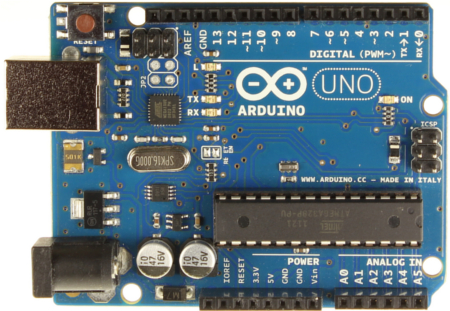
Arduino Uno

Arduino BT (Bluetooth)

El Arduino BT es una placa originariamente basada sobre el ATmega168, pero ahora esta basada sobre el ATmega328 (datasheet) y el modelo bluetooth Bluegiga WT11 (detalles y datasheet [pdf]). Permite una comunicacion seriale sin cables atraves el bluetooth (pero no es compatible con auriculares bluetooth o otros dispositivos). Tiene 14 I/O digitales (6 de los cuales pueden ser utilizados como salida PWM, uno para reiniciar el modulo WT11 sobre la placa), 6 input analogicos, un cristal de 16Mhz, terminales de potencia, una cabecera ICSP, un botón de reinicio. Tiene todo lo necesario para apoyar el microcontrolador y se puede programar a través de la conexión Bluetooth. Instrucciones disponibles (en ingles) en la sección getting started with the Arduino BT.

Descripción adicionalMás Detalles

Especificaciones técnicas

Microcontrolador ATmega328
Tension de operación 5V
Tensión de entrada 2.5-12V
I/O digitales 14 (6 de lo cuales con salida PWM)
entradas analogicas 6
Corriente de salida para I/O Pin 40 mA
Corriente de salida para 3.3V Pin 500 mA (con sorgente a 1.5A)
Corriente de salida para 5V Pin 1000 mA (con sorgente a 1.5A)
Flash Memory 32 KB (of which 2 KB used by bootloader)
SRAM 2 KB
EEPROM 1 KB
Clock Speed 16 MHz
Modulo BT 2.1 WT11i-A-AI4

Para obtener una descripción más detallada sobre su placa usted debe visitar la página oficial Arduino Bluetooth page en la sección Hardware.

Power

The Arduino BT can be powered via the V+ and GND screw terminals. The board contains a DC-DC convector that allows it to be powered with as little as 2.5V, a maximum of 12V. Higher voltages or reversed polarity in the power supply can damage or destroy the board. The protection for reverse polarity connection is ONLY on the screw terminal. The power pins are as follows:

  • +VIN. The input voltage to the Arduino board (i.e. the same as the V+ screw terminal). You can supply voltage through this pin, or, if supplying voltage via the screw terminals, access it through this pin. Warning: The protection for reverse polarity connection is ONLY on the screw terminal, do not attach negative voltages to this pin. It will damage the board.
  • 5V. This pin outputs a regulated 5V from the regulator on the board. The board can be supplied with power either from the screw terminal (2.5V – 12V) or the VIN pin of the board (2.5V-12V). Supplying voltage via the 5V or 3.3V pins bypasses the regulator, and can damage your board. We don’t advise it.
  • GND. Ground pins.

Memory

The ATmega328 has 32 KB of flash memory for storing code (of which 2 KB is used for the bootloader). It has 1 KB of SRAM and 512 bytes of EEPROM (which can be read and written with the EEPROM library).

Input and Output

Each of the 14 digital pins on the BT can be used as an input or output, using pinMode()digitalWrite(), and digitalRead()functions. They operate at 5 volts. Each pin can provide or receive a maximum of 40 mA and has an internal pull-up resistor (disconnected by default) of 20-50 kOhms. In addition, some pins have specialized functions:

  • Serial: 0 (RX) and 1 (TX). Used to receive (RX) and transmit (TX) TTL serial data. These pins are connected to the corresponding pins of the Bluegiga WT11 module.
  • External Interrupts: 2 and 3. These pins can be configured to trigger an interrupt on a low value, a rising or falling edge, or a change in value. See the attachInterrupt() function for details.
  • PWM: 3, 5, 6, 9, 10, and 11. Provide 8-bit PWM output with the analogWrite() function.
  • SPI: 10 (SS), 11 (MOSI), 12 (MISO), 13 (SCK). These pins support SPI communication, which, although provided by the underlying hardware, is not currently included in the Arduino language.
  • BT Reset: 7. Connected to the reset line of the Bluegiga WT11 module, which is active high.
  • LED: 13. There is a built-in LED connected to digital pin 13. When the pin is HIGH value, the LED is on, when the pin is LOW, it’s off.

The BT has 6 analog inputs, each of which provide 10 bits of resolution (i.e. 1024 different values). By default they measure from ground to 5 volts, though is it possible to change the upper end of their range using the AREF pin and some low-level code. Additionally, some pins have specialized functionality:

  • I2C: 4 (SDA) and 5 (SCL). Support I2C (TWI) communication using the Wire library (documentation on the Wiring website).

There are a couple of other pins on the board:

  • AREF. Reference voltage for the analog inputs. Used with analogReference().

See also the mapping between Arduino pins and ATmega168/328 ports.

Bluetooth Communication

The Bluegiga WT11 module on the Arduino BT provides Bluetooth communication with computers, phones, and other Bluetooth devices. The WT11 communicates with the ATmega328 via serial (shared with the RX and TX pins on the board). It comes configured for 115200 baud communication. The module should be configurable and detectable by your operating system’s bluetooth drivers, which should then provide a virtual com port for use by other applications. The Arduino software includes a serial monitor which allows simple textual data to be sent to and from the Arduino board over this bluetooth connection. The board can also be reprogrammed using this same wireless connection. The WT11 is specially configured for use in the Arduino BT. Its name is set to ARDUINOBT and passcode to 12345. For details, see the complete initialization sketch.

Communication

The Arduino BT has a number of other facilities for communicating. The ATmega328’s UART TTL (5V) serial communication is available on digital pins 0 (RX) and 1 (TX) as well as being connected to the WT11 module. A SoftwareSerial library allows for serial communication on any of the BT’s digital pins. The ATmega328 also supports I2C (TWI) and SPI communication. The Arduino software includes a Wire library to simplify use of the I2C bus; see the documentation on the Wiring website for details. To use the SPI communication, please see theATmega328 datasheet.

Programming

The Arduino BT can be programmed with the Arduino software (download). For details, see the reference and tutorials. The ATmega328 on the Arduino BT comes preburned with a bootloader that allows you to upload new code to it without the use of an external hardware programmer. It communicates using the original STK500 protocol (referenceC header files). You can also bypass the bootloader and program the ATmega328 through the ICSP (In-Circuit Serial Programming) header; see these instructions for details.

Physical Characteristics

The maximum length and width of the BT are approximately 3.2 and 2.1 inches respectively. Three screw holes allow the board to be attached to a surface or case. Note that the distance between digital pins 7 and 8 is 160 mil (0.16″), not an even multiple of the 100 mil spacing of the other pins.

Precio: $122.01

Loading Actualizando Carro…

Arduino Esplora

El Arduino Esplora es una placa ya lista para usar, muy fácil de manejar, que te permite explorar un sinfín de posibilidades que hay en el mundo de los sensores y actuadores, sin tener que usar breadboards (protoboards), soldadores o cables.

No hay límites para las aplicaciones educativas y divertidas que puedes desarrollar. Si lo necesitas puedes agregar además un par de sensores y actuadores adicionales. ¡Añadiendo un módulo LCD de colores podrás crear video juegos divertidos en tu propia consola de código abierto!

El Arduino Esplora combina el procesador Arduino con una gama de sensores y actuadores incluidos :

  • sensores de luz
  • sensores de temperatura
  • accelerometros de 3 ejes
  • joystick
  •  pulsadores
  • potenciometros lineares
  • leds RGB
  • zumbadores
Descripción adicionalMás Detalles

El Arduino Esplora puede emular un ratón o un teclado, te permite crear tu propio controlador de software para música, herramientas 3D, o incluso un procesador de textos. El Arduino Esplora viene ya pre-programado con una secuencia de instrucciones de juego, así que tan pronto como lo conectes a tu ordenador puedes comenzar a jugar de inmediato. Para más detalle por favor visita arduino.cc/esplora.

Detalles tecnicos

Microcontroller ATmega32u4
Operating Voltage 5V
Flash Memory 32 KB of which 4 KB used by bootloader
SRAM 2.5 KB
EEPROM 1 KB
Clock Speed 16 MHz

Lleva incluido el cable MICRO USB.

The Arduino Esplora is a microcontroller board derived from the Arduino Leonardo. The Esplora differs from all preceding Arduino boards in that it provides a number of built-in, ready-to-use setof onboard sensors for interaction. It’s designed for people who want to get up and running with Arduino without having to learn about the electronics first. For a step-by-step introduction to the Esplora, check out the Getting Started with Esplora guide.

The Esplora has onboard sound and light outputs, and several input sensors, including a joystick, a slider, a temperature sensor, an accelerometer, a microphone, and a light sensor. It also has the potential to expand its capabilities with two Tinkerkit input and output connectors, and a socket for a color TFT LCD screen.

Like the Leonardo board, the Esplora uses an Atmega32U4 AVR microcontroller with 16 MHz crystal oscillator and a micro USB connection capable of acting as a USB client device, like a mouse or a keyboard.

In the upper left corner of the board there is a reset pushbutton, that you can use to restart the board. There are four status LEDS :

  • ON [green] indicates whether the board is receiving power supply
  • L [yellow] connected directly to the microcontroller, accessible through pin 13
  • RX and TX [yellow] indicates the data being transmitted or received over the USB communication

The board contains everything needed to support the microcontroller; simply connect it to a computer with a USB cable to get started.

Schematic & Reference Design

EAGLE files: Attach:arduino-esplora-reference-design.zip
Schematic: Attach:arduino-esplora-schematic.pdf

Memory

The ATmega32u4 has 32 KB (with 4 KB used for the bootloader). It also has 2.5 KB of SRAM and 1 KB of EEPROM (which can be read and written with the EEPROM library).

Input and Output:

The design of the Esplora board recalls traditional gamepad design with an analog joystick on the left and four pushbuttons on the right.

The Esplora has the following on-board inputs and outputs :

  • Analog joystick with central push-button two axis (X and Y) and a center pushbutton.
  • 4 push-buttons laid out in a diamond pattern.
  • Linear potentiometer slider near the bottom of the board.
  • Microphone for getting the loudness (amplitude) of the surrounding environment.
  • Light sensor for getting the brightness.
  • Temperature sensor reads the ambient temperature
  • Three-axis accelerometer measures the board’s relation to gravity on three axes (X, Y, and Z)
  • Buzzer can produce square-waves.
  • RGB led bright LED with Red Green and Blue elements for color mixing.
  • 2 TinkerKit Inputs to connect the TinkerKit sensor modules with the 3-pin connectors.
  • 2 TinkerKit Outputs to connect the TinkerKit actuator modules with the 3-pin connectors.
  • TFT display connector connector for an optional color LCD screen, SD card, or other devices that use the SPI protocol.

In order to utilize the total number of available sensors, the board uses an analog multiplexer. This means a single analog input of the microcontroller is shared among all the input channels (except the 3-axis accelerometer). Four additional microcontroller pins choose which channel to read.

Communication

The Leonardo the Esplora has a number of facilities for communicating with a computer, another Arduino, or other microcontrollers. The ATmega32U4 provides serial (CDC) communication over USB and appears as a virtual com port to software on the computer. The chip also acts as a full speed USB 2.0 device, using standard USB COM drivers. On Windows, a .inf file is required. The Arduino software includes a serial monitor which allows simple textual data to be sent to and from the Arduino board. The RX and TX LEDs on the board will flash when data is being transmitted via the USB connection to the computer.

The ATmega32U4 also supports SPI communication, that can be accessed through the SPI library.

The Esplora can appear as a generic keyboard and mouse, and can be programmed to control these input devices using theKeyboard and Mouse libraries.

Programming

The Esplora can be programmed with the Arduino software (download). Select «Arduino Esplora» from the Tools > Board menu. For details, see the getting started page.

The ATmega32U4 on the Arduino Esplora comes preburned with a bootloader that allows you to upload new code to it without the use of an external hardware programmer. It communicates using the AVR109 protocol.

You can also bypass the bootloader and program the microcontroller through the ICSP (In-Circuit Serial Programming) header; see these instructions for details.

Esplora Library

To facilitate writing sketches for the Esplora, there is a dedicated library that contains methods for reading the sensors and writing to the outputs on-board.

The library offers high level methods which provide pre-processed data, like degrees Fahrenheit or Celsius from the temperature sensor. It also enables easy access to the outputs, like writing values to the RGB LED.

Visit the Esplora library reference page to see the complete documentation of the library and examples.

Automatic (Software) Reset and Bootloader Initiation

Rather than requiring a physical press of the reset button before an upload, the Esplora is designed in a way that allows it to be reset by software running on a connected computer. The reset is triggered when the Esplora’s virtual (CDC) serial / COM port is opened at 1200 baud and then closed. When this happens, the processor will reset, breaking the USB connection to the computer (meaning that the virtual serial / COM port will disappear). After the processor resets, the bootloader starts, remaining active for about 8 seconds. The bootloader can also be initiated by pressing the reset button on the Esplora. Note that when the board first powers up, it will jump straight to the user sketch, if present, rather than initiating the bootloader.

Because of the way the Esplora handles reset it’s best to let the Arduino software try to initiate the reset before uploading, especially if you are in the habit of pressing the reset button before uploading on other boards. If the software can’t reset the board you can always start the bootloader by pressing the reset button on the board.

USB Overcurrent Protection

The Esplora has a resettable polyfuse that protects your computer’s USB ports from shorts and overcurrent. Although most computers provide their own internal protection, the fuse provides an extra layer of protection. If more than 500 mA is applied to the USB port, the fuse will automatically break the connection until the short or overload is removed.

Physical Characteristics

The maximum length and width of the Esplora PCB are 6.5 and 2.4 inches respectively, with the USB and TinkerKitconnectors extending beyond the latter dimension. Four screw holes allow the board to be attached to a surface or case.

Precio: $82.54

Loading Actualizando Carro…

Arduino Original Uno R3

The Arduino Uno is a microcontroller board based on the ATmega328 (datasheet). It has 14 digital input/output pins (of which 6 can be used as PWM outputs), 6 analog inputs, a 16 MHz ceramic resonator, a USB connection, a power jack, an ICSP header, and a reset button. It contains everything needed to support the microcontroller; simply connect it to a computer with a USB cable or power it with a AC-to-DC adapter or battery to get started.

Descripción adicionalMás Detalles

The Uno differs from all preceding boards in that it does not use the FTDI USB-to-serial driver chip. Instead, it features the Atmega16U2 (Atmega8U2 up to version R2) programmed as a USB-to-serial converter. Revision 2 of the Uno board has a resistor pulling the 8U2 HWB line to ground, making it easier to put into . Revision 3 of the board has the following new features:

  • 1.0 pinout: added SDA and SCL pins that are near to the AREF pin and two other new pins placed near to the RESET pin, the IOREF that allow the shields to adapt to the voltage provided from the board. In future, shields will be compatible both with the board that use the AVR, which operate with 5V and with the Arduino Due that operate with 3.3V. The second one is a not connected pin, that is reserved for future purposes.
  • Stronger RESET circuit.
  • Atmega 16U2 replace the 8U2.
«Uno» means one in Italian and is named to mark the upcoming release of Arduino 1.0. The Uno and version 1.0 will be the reference versions of Arduino, moving forward. The Uno is the latest in a series of USB Arduino boards, and the reference model for the Arduino platform; for a comparison with previous versions, see the index of Arduino boards?.

Summary

Microcontroller ATmega328
Operating Voltage 5V
Input Voltage (recommended) 7-12V
Input Voltage (limits) 6-20V
Digital I/O Pins 14 (of which 6 provide PWM output)
Analog Input Pins 6
DC Current per I/O Pin 40 mA
DC Current for 3.3V Pin 50 mA
Flash Memory 32 KB (ATmega328) of which 0.5 KB used by bootloader
SRAM 2 KB (ATmega328)
EEPROM 1 KB (ATmega328)
Clock Speed 16 MHz

Precio: $31.03

Loading Actualizando Carro…