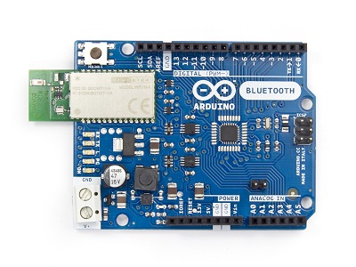
El Arduino BT es una placa originariamente basada sobre el ATmega168, pero ahora esta basada sobre el ATmega328 (datasheet) y el modelo bluetooth Bluegiga WT11 (detalles y datasheet [pdf]). Permite una comunicacion seriale sin cables atraves el bluetooth (pero no es compatible con auriculares bluetooth o otros dispositivos). Tiene 14 I/O digitales (6 de los cuales pueden ser utilizados como salida PWM, uno para reiniciar el modulo WT11 sobre la placa), 6 input analogicos, un cristal de 16Mhz, terminales de potencia, una cabecera ICSP, un botón de reinicio. Tiene todo lo necesario para apoyar el microcontrolador y se puede programar a través de la conexión Bluetooth. Instrucciones disponibles (en ingles) en la sección getting started with the Arduino BT.
Especificaciones técnicas
| Microcontrolador | ATmega328 |
| Tension de operación | 5V |
| Tensión de entrada | 2.5-12V |
| I/O digitales | 14 (6 de lo cuales con salida PWM) |
| entradas analogicas | 6 |
| Corriente de salida para I/O Pin | 40 mA |
| Corriente de salida para 3.3V Pin | 500 mA (con sorgente a 1.5A) |
| Corriente de salida para 5V Pin | 1000 mA (con sorgente a 1.5A) |
| Flash Memory | 32 KB (of which 2 KB used by bootloader) |
| SRAM | 2 KB |
| EEPROM | 1 KB |
| Clock Speed | 16 MHz |
| Modulo BT | 2.1 WT11i-A-AI4 |
Para obtener una descripción más detallada sobre su placa usted debe visitar la página oficial Arduino Bluetooth page en la sección Hardware.
Power
The Arduino BT can be powered via the V+ and GND screw terminals. The board contains a DC-DC convector that allows it to be powered with as little as 2.5V, a maximum of 12V. Higher voltages or reversed polarity in the power supply can damage or destroy the board. The protection for reverse polarity connection is ONLY on the screw terminal. The power pins are as follows:
- +VIN. The input voltage to the Arduino board (i.e. the same as the V+ screw terminal). You can supply voltage through this pin, or, if supplying voltage via the screw terminals, access it through this pin. Warning: The protection for reverse polarity connection is ONLY on the screw terminal, do not attach negative voltages to this pin. It will damage the board.
- 5V. This pin outputs a regulated 5V from the regulator on the board. The board can be supplied with power either from the screw terminal (2.5V - 12V) or the VIN pin of the board (2.5V-12V). Supplying voltage via the 5V or 3.3V pins bypasses the regulator, and can damage your board. We don't advise it.
- GND. Ground pins.
Memory
The ATmega328 has 32 KB of flash memory for storing code (of which 2 KB is used for the bootloader). It has 1 KB of SRAM and 512 bytes of EEPROM (which can be read and written with the EEPROM library).
Input and Output
Each of the 14 digital pins on the BT can be used as an input or output, using pinMode(), digitalWrite(), and digitalRead()functions. They operate at 5 volts. Each pin can provide or receive a maximum of 40 mA and has an internal pull-up resistor (disconnected by default) of 20-50 kOhms. In addition, some pins have specialized functions:
- Serial: 0 (RX) and 1 (TX). Used to receive (RX) and transmit (TX) TTL serial data. These pins are connected to the corresponding pins of the Bluegiga WT11 module.
- External Interrupts: 2 and 3. These pins can be configured to trigger an interrupt on a low value, a rising or falling edge, or a change in value. See the attachInterrupt() function for details.
- PWM: 3, 5, 6, 9, 10, and 11. Provide 8-bit PWM output with the analogWrite() function.
- SPI: 10 (SS), 11 (MOSI), 12 (MISO), 13 (SCK). These pins support SPI communication, which, although provided by the underlying hardware, is not currently included in the Arduino language.
- BT Reset: 7. Connected to the reset line of the Bluegiga WT11 module, which is active high.
- LED: 13. There is a built-in LED connected to digital pin 13. When the pin is HIGH value, the LED is on, when the pin is LOW, it's off.
The BT has 6 analog inputs, each of which provide 10 bits of resolution (i.e. 1024 different values). By default they measure from ground to 5 volts, though is it possible to change the upper end of their range using the AREF pin and some low-level code. Additionally, some pins have specialized functionality:
- I2C: 4 (SDA) and 5 (SCL). Support I2C (TWI) communication using the Wire library (documentation on the Wiring website).
There are a couple of other pins on the board:
- AREF. Reference voltage for the analog inputs. Used with analogReference().
See also the mapping between Arduino pins and ATmega168/328 ports.
Bluetooth Communication
The Bluegiga WT11 module on the Arduino BT provides Bluetooth communication with computers, phones, and other Bluetooth devices. The WT11 communicates with the ATmega328 via serial (shared with the RX and TX pins on the board). It comes configured for 115200 baud communication. The module should be configurable and detectable by your operating system's bluetooth drivers, which should then provide a virtual com port for use by other applications. The Arduino software includes a serial monitor which allows simple textual data to be sent to and from the Arduino board over this bluetooth connection. The board can also be reprogrammed using this same wireless connection. The WT11 is specially configured for use in the Arduino BT. Its name is set to ARDUINOBT and passcode to 12345. For details, see the complete initialization sketch.
Communication
The Arduino BT has a number of other facilities for communicating. The ATmega328's UART TTL (5V) serial communication is available on digital pins 0 (RX) and 1 (TX) as well as being connected to the WT11 module. A SoftwareSerial library allows for serial communication on any of the BT's digital pins. The ATmega328 also supports I2C (TWI) and SPI communication. The Arduino software includes a Wire library to simplify use of the I2C bus; see the documentation on the Wiring website for details. To use the SPI communication, please see theATmega328 datasheet.
Programming
The Arduino BT can be programmed with the Arduino software (download). For details, see the reference and tutorials. The ATmega328 on the Arduino BT comes preburned with a bootloader that allows you to upload new code to it without the use of an external hardware programmer. It communicates using the original STK500 protocol (reference, C header files). You can also bypass the bootloader and program the ATmega328 through the ICSP (In-Circuit Serial Programming) header; see these instructions for details.
Physical Characteristics
The maximum length and width of the BT are approximately 3.2 and 2.1 inches respectively. Three screw holes allow the board to be attached to a surface or case. Note that the distance between digital pins 7 and 8 is 160 mil (0.16"), not an even multiple of the 100 mil spacing of the other pins.


